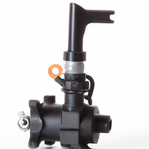
Understanding Fuel Sender Assembly: Components, Working Principle, Troubleshooting, and Maintenance
Introduction to Fuel Sender Assembly
Fuel sender assembly is a crucial component of the fuel system in a vehicle that measures the amount of fuel in the tank and sends the signal to the fuel gauge. Understanding the fuel sender assembly and its components can help you diagnose and fix fuel level reading issues in your vehicle.
Definition of Fuel Sender Assembly
A fuel sender assembly is a device that measures the fuel level in a vehicle’s tank and sends a signal to the fuel gauge. The fuel sender assembly is usually located inside the fuel tank and consists of several components, including a float arm, a pivot, a resistance element, and a wiring harness.
Importance of Fuel Sender Assembly
Accurate fuel level readings are essential for drivers to monitor their fuel usage and avoid running out of fuel while driving. Fuel sender assembly plays a crucial role in ensuring that the fuel gauge provides accurate readings. A faulty fuel sender assembly can cause inaccurate fuel level readings, which can lead to unexpected breakdowns and inconvenience for drivers.
Common Types of Fuel Sender Assembly
There are two types of fuel sender assembly commonly used in vehicles: the mechanical type and the electrical type. The mechanical type uses a float arm and pivot to measure the fuel level and directly connects to the fuel gauge. The electrical type uses a fuel level sensor to measure the fuel level and sends a signal to the fuel gauge through a wiring harness.
In the next chapter, we’ll take a closer look at the components of the fuel sender assembly and their functions.
Components of Fuel Sender Assembly
Understanding the components of the fuel sender assembly is essential to troubleshoot and maintain this critical component of the fuel system in a vehicle.
Overview of the Components
The fuel sender assembly consists of several components, including a float arm, pivot, resistance element, wiring harness, and connectors. The float arm and pivot move with the fuel level changes in the tank, while the resistance element converts the float arm movement into an electrical signal. The wiring harness and connectors transmit the electrical signal to the fuel gauge.
Fuel Level Sensor
The fuel level sensor is the component responsible for measuring the fuel level in the tank. The fuel level sensor can use different technologies, such as ultrasonic, capacitive, or resistive, to measure the fuel level. The fuel level sensor is usually located inside the fuel tank and can be accessed by removing the fuel pump assembly.
Float Arm, Pivot, and Resistance Element
The float arm is a buoyant arm that moves up and down with the fuel level changes in the tank. The pivot supports the float arm and allows it to move smoothly. The resistance element is a variable resistor that converts the movement of the float arm into an electrical signal. The resistance element can be a potentiometer, a rheostat, or a wire-wound resistor.
Wiring Harness and Connectors
The wiring harness and connectors transmit the electrical signal from the resistance element to the fuel gauge. The wiring harness is usually made of several wires that connect the fuel sender assembly to the fuel pump assembly or the main wiring harness. The connectors ensure a secure and reliable connection between the wiring harness and the fuel gauge.
In the next chapter, we’ll explore the working principle of the fuel sender assembly in detail.
Working Principle of Fuel Sender Assembly
The fuel sender assembly works on a simple principle of converting the fuel level changes in the tank into an electrical signal that is transmitted to the fuel gauge. Let’s take a closer look at the working principle of the fuel sender assembly.
How Fuel Sender Assembly Works
As the fuel level changes in the tank, the float arm attached to the pivot moves up and down. The float arm is connected to a resistance element, which converts the movement of the float arm into an electrical signal. The electrical signal is transmitted through the wiring harness and connectors to the fuel gauge, which displays the fuel level.
Electrical Signal Conversion
The resistance element can use different methods to convert the movement of the float arm into an electrical signal. For example, a potentiometer uses a variable resistor that changes its resistance based on the float arm’s position. A rheostat uses a wire-wound resistor that varies the resistance based on the float arm’s movement.
Signal Transmission and Display
The electrical signal generated by the resistance element is transmitted through the wiring harness and connectors to the fuel gauge. The fuel gauge displays the fuel level using a needle or a digital display. The fuel gauge can be calibrated to provide accurate readings by adjusting the resistance value of the fuel sender assembly.
Accuracy and Calibration
The accuracy of the fuel sender assembly depends on several factors, such as the type of fuel level sensor, the design of the float arm, and the resistance value of the resistance element. Calibration of the fuel sender assembly is essential to ensure accurate fuel level readings. Calibration can be done by adjusting the resistance value of the fuel sender assembly using a multimeter and a calibration chart.
In the next chapter, we’ll discuss some common issues that can arise with the fuel sender assembly and how to troubleshoot them.
Troubleshooting Fuel Sender Assembly
The fuel sender assembly is a critical component of the fuel system in a vehicle, and any issues with it can lead to inaccurate fuel level readings and affect the vehicle’s performance. Let’s take a look at some common issues that can arise with the fuel sender assembly and how to troubleshoot them.
Inaccurate Fuel Level Readings
One of the most common issues with the fuel sender assembly is inaccurate fuel level readings. This can happen due to several reasons, such as a faulty fuel level sensor, a damaged float arm, or a loose connector. To troubleshoot this issue, you can perform the following steps:
- Check the wiring harness and connectors for any damage or looseness.
- Use a multimeter to check the resistance value of the fuel sender assembly and compare it to the calibration chart.
- Check the fuel level sensor for any damage or corrosion.
Fuel Gauge Not Working
Another common issue with the fuel sender assembly is the fuel gauge not working. This can happen due to a faulty fuel gauge, a blown fuse, or a loose connection. To troubleshoot this issue, you can perform the following steps:
- Check the fuse for the fuel gauge and replace it if necessary.
- Use a multimeter to check the voltage at the fuel gauge and compare it to the specification.
- Check the wiring harness and connectors for any damage or looseness.
Erratic Fuel Level Readings
Sometimes the fuel gauge may display erratic fuel level readings, jumping up and down or fluctuating. This can happen due to a damaged float arm, a faulty fuel level sensor, or a loose connector. To troubleshoot this issue, you can perform the following steps:
- Check the float arm and pivot for any damage or wear.
- Check the fuel level sensor for any damage or corrosion.
- Check the wiring harness and connectors for any damage or looseness.
In the next chapter, we’ll discuss some best practices for maintaining the fuel sender assembly and extending its lifespan.
Maintaining and Extending the Lifespan of Fuel Sender Assembly
Regular maintenance of the fuel sender assembly can help extend its lifespan and prevent issues such as inaccurate fuel level readings or fuel gauge malfunction. Let’s take a look at some best practices for maintaining and extending the lifespan of the fuel sender assembly.
Clean the Fuel Tank Regularly
Cleaning the fuel tank regularly can prevent debris or sediment from clogging the fuel sender assembly or causing damage to the float arm. It is recommended to clean the fuel tank at least once a year or more frequently if you notice any issues with the fuel system.
Replace Fuel Filter
Replacing the fuel filter at regular intervals can prevent debris or contaminants from reaching the fuel sender assembly and causing damage or malfunction. It is recommended to replace the fuel filter every 10,000 to 15,000 miles or as per the manufacturer’s recommendation.
Check Fuel Sender Assembly During Routine Maintenance
During routine maintenance of the vehicle, such as oil change or tire rotation, it is recommended to check the fuel sender assembly for any damage or wear. You can use a multimeter to check the resistance value of the fuel sender assembly and compare it to the calibration chart. Also, check the float arm and pivot for any damage or wear.
Use High-Quality Fuel
Using high-quality fuel can prevent the buildup of deposits or contaminants in the fuel system, including the fuel sender assembly. It is recommended to use fuel that meets the manufacturer’s specifications and avoid using fuel with additives or low-quality fuel.
Protect Fuel Sender Assembly from Damage
Protecting the fuel sender assembly from damage, such as impacts or exposure to extreme temperatures, can prevent issues such as inaccurate fuel level readings or fuel gauge malfunction. It is recommended to park the vehicle in a safe location and avoid driving over rough terrain or potholes.
By following these best practices for maintaining and extending the lifespan of the fuel sender assembly, you can ensure accurate fuel level readings and avoid costly repairs.
For detailed information, you can contact us at torqueusa.com.


